Piping Isometric Drawing Symbols
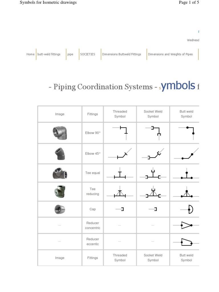
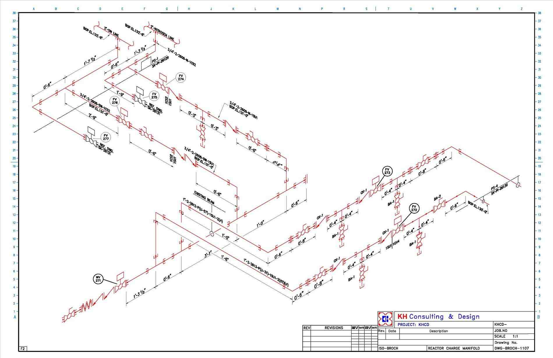
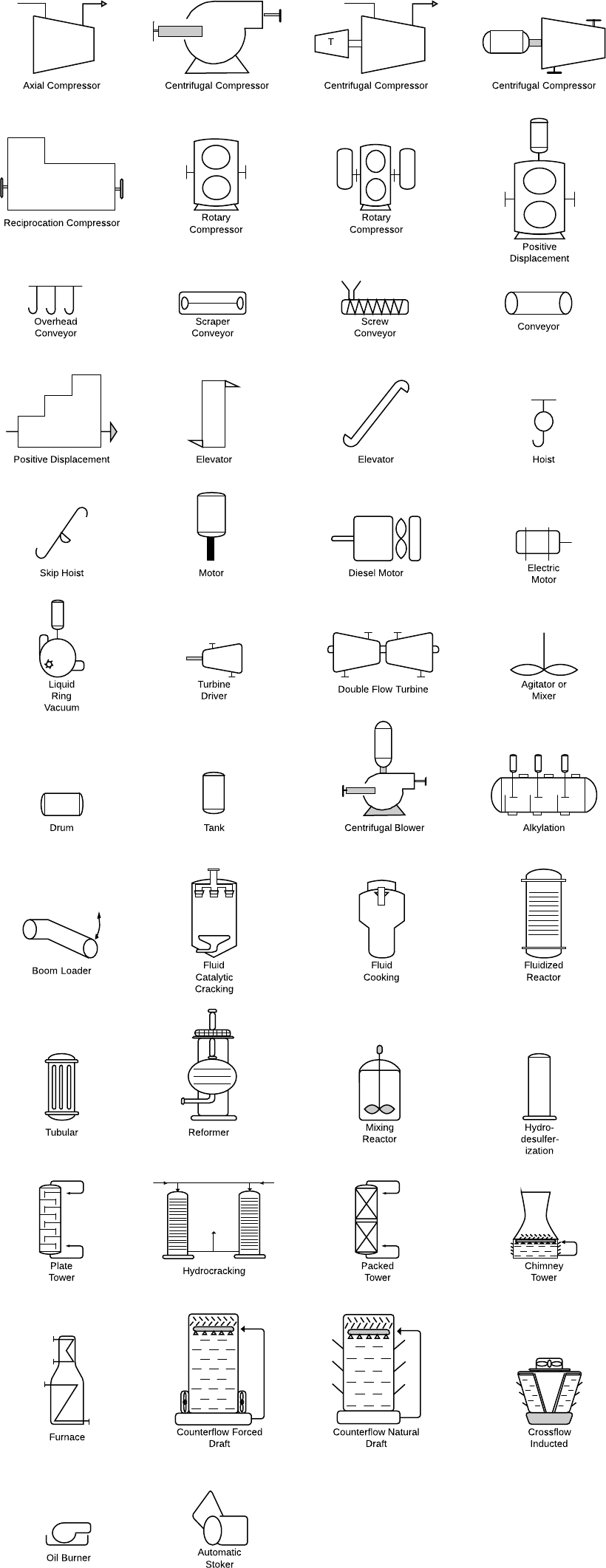
Piping Isometric Drawing Symbols - Works with inch or millimeter drawing units. Web various symbols are used to indicate piping components, instrumentation, equipments in engineering drawings such as piping and instrumentation diagram (p&id), isometric drawings, plot plan, equipment layout, welding drawings etc. The direction should be selected so as to facilitate easy checking of isometrics with ga. Structural reference points that provide location can be shown on isometric. The process of generating a piping. Gives the mechanical symbols in isometric drawings. Web piping symbols for isometric drawings. What is an isometric ? Every project has specific requirements. Specifies the ratio of the drawing’s size to the actual size of the components. Isometrics are usually drawn from information found on a plan and elevation views. Web unlike orthographic drawings, piping isometric drawings allow the pipe line to be drawn in a manner by which the length, width and depth are shown in a single view. Web mechanical symbols for isometric drawings. These needs to be reflected in isometrics drawings. Inlet/outlet bolt scope of supply. The direction should be selected so as to facilitate easy checking of isometrics with ga. Web piping symbols for isometric drawings. Isometrics are usually drawn from information found on a plan and sectional elevation views. Lighter lines show connected pipe, and are not parts of the symbols. In the world of industrial projects, precision and accuracy are of utmost importance. Symbols are shown in black lines. Web piping isometric drawing symbols for reading and understanding a piping isometric drawing, one should learn the piping isometric drawing symbols thoroughly. Reference number of pefs (p&id), ga drawings, line numbers, the direction of flow, and insulation tracing. Web unlike orthographic drawings, piping isometric drawings allow the pipe line to be drawn in a. Unlike orthographics, piping isometrics allow the pipe to be drawn in a manner by which the length, width and depth are shown in a single view. Web piping isometric drawings are detailed technical illustrations that show a 3d view of piping systems. Web piping isometric drawing symbols for reading and understanding a piping isometric drawing, one should learn the piping. Web piping isometric dwg symbols designed just for you in autocad. Some of these requirements can be regarding following points. Web isometric symbols for piping fittings. Isometrics are usually drawn from information found on a plan and elevation views. The direction should be selected so as to facilitate easy checking of isometrics with ga. Automatically set the grid and snap with a click of the mouse. Isometrics are usually drawn from information found on a plan and elevation views. Web piping isometric drawing symbols for reading and understanding a piping isometric drawing, one should learn the piping isometric drawing symbols thoroughly. Piping isometric drawing is a representation of 3d view of piping layout of. Gives the mechanical symbols in isometric drawings. Web the following information must be included in piping isometric drawings: What is an isometric ? Web isometric drawings are typically used to show the details of a piping system, such as the size and type of piping, the direction of flow of the fluids, and the location of valves, pumps, and other. Automatically set the grid and snap with a click of the mouse. Web isometric symbols for piping fittings. In this dwg file you will find a huge collection of pipeline isometric drawings which are created in 2d format. Reference number of pefs (p&id), ga drawings, line numbers, the direction of flow, and insulation tracing. The process of generating a piping. Every project has specific requirements. Web various symbols are used to indicate piping components, instrumentation, equipments in engineering drawings such as piping and instrumentation diagram (p&id), isometric drawings, plot plan, equipment layout, welding drawings etc. Web isometric symbols for piping fittings. Works with inch or millimeter drawing units. These needs to be reflected in isometrics drawings. Web piping isometric drawings are detailed technical illustrations that show a 3d view of piping systems. Contains 1,120 isometric piping symbols in.dwg format. The drawing axes of the isometrics intersect at an angle of 60°. Web piping isometric drawing symbols for various markings. Web isometric symbols for piping fittings. Web isometric drawings are typically used to show the details of a piping system, such as the size and type of piping, the direction of flow of the fluids, and the location of valves, pumps, and other equipment nozzles. Usually, all these piping and pipeline drawing symbols are constant and do not vary much from one organization to another. Fittings,. Specifies the ratio of the drawing’s size to the actual size of the components. Usually, all these piping and pipeline drawing symbols are constant and do not vary much from one organization to another. Knowing legends and symbols that are universal for reading a piping isometric drawing is much helpful to gain info about the piping material or piping fittings. Web a piping isometric drawing is a technical drawing that depicts a pipe spool or a complete pipeline using an isometric representation. Symbols are shown in black lines. These highly structured drawings provide a comprehensive 3d representation of the arrangement, dimensions, and connections of pipes within a system. Web the following information must be included in piping isometric drawings: Web various symbols are used to indicate piping components, instrumentation, equipments in engineering drawings such as piping and instrumentation diagram (p&id), isometric drawings, plot plan, equipment layout, welding drawings etc. The drawing axes of the isometrics intersect at an angle of 60°. Every project has specific requirements. Lighter lines show connected pipe, and are not parts of the symbols. The symbols that represent fittings, valves and flanges are modified to adapt to the isometric grid. Usually, all these piping and pipeline drawing symbols are constant and do not vary much from one organization to another. The process of generating a piping. What is an isometric ? Web isometric symbols for piping fittings. These needs to be reflected in isometrics drawings. In this dwg file you will find a huge collection of pipeline isometric drawings which are created in 2d format. Fittings, flanges, and valves play essential roles in pipeline isometric drawings, each with unique symbols according to iso standards.
Piping Isometric Drawing Symbols Pdf at Explore

Piping Isometric Drawings The Piping Engineering World

Piping symbols for isometric drawing vsamarketing
How To Use A Ridgid Pipe Threading Machine Piping Symbols For

PIPE FITTING ISOMETRIC CAD Block And Typical Drawing
Piping Isometric Drawing Symbols Pdf at Explore

How to read isometric drawing piping dadver

Valves Symbols used in P&ID and Piping Isometric drawings YouTube
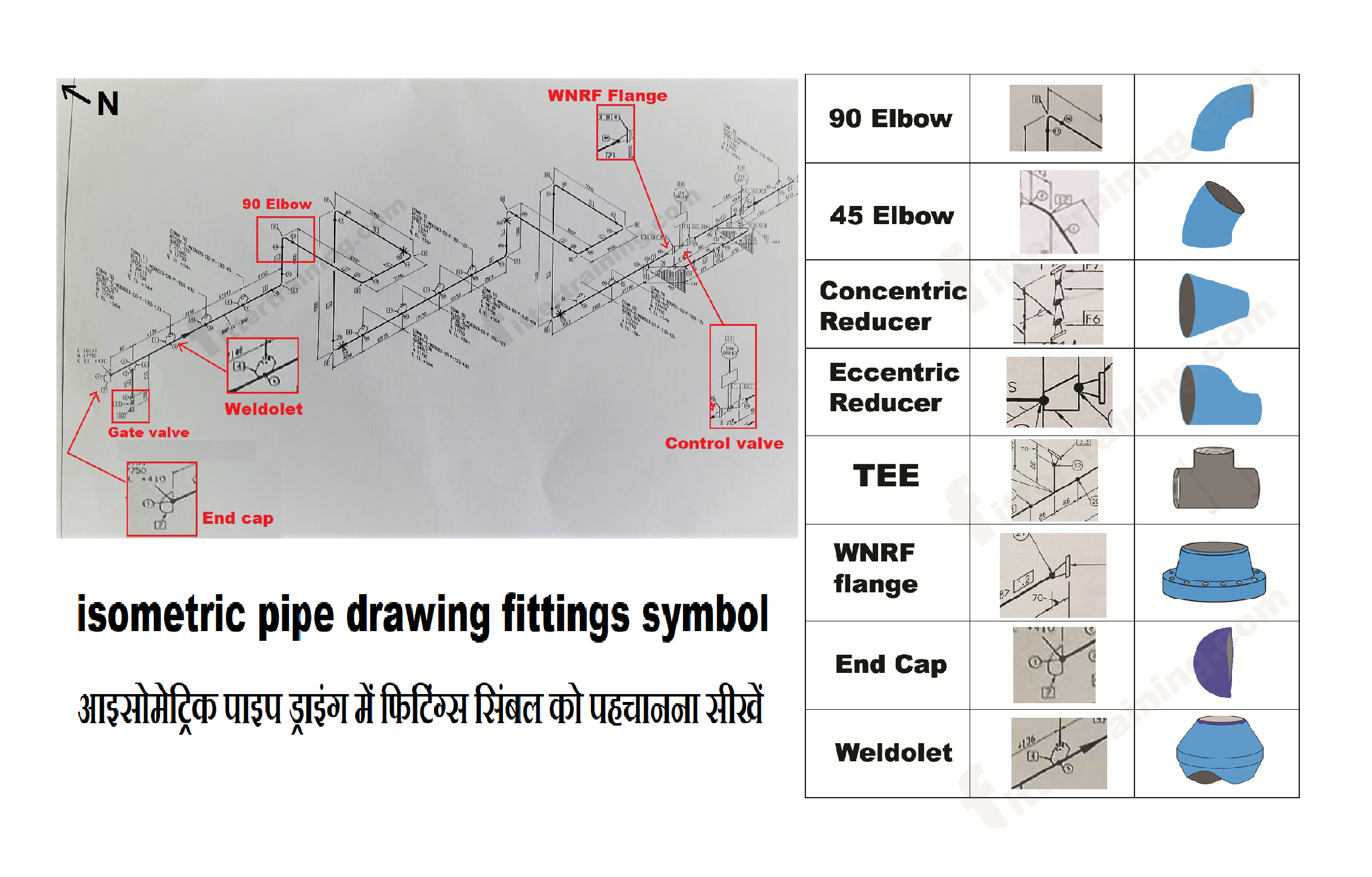
isometric pipe drawing fittings symbol Fitter training
Symbols for Isometric Pipe (Fluid Conveyance)
Isometrics Are Usually Drawn From Information Found On A Plan And Sectional Elevation Views.
Isometrics Are Usually Drawn From Information Found On A Plan And Elevation Views.
Web Piping Isometric Drawing Symbols For Reading And Understanding A Piping Isometric Drawing, One Should Learn The Piping Isometric Drawing Symbols Thoroughly.
Gives The Mechanical Symbols In Isometric Drawings.
Related Post: